Translate:

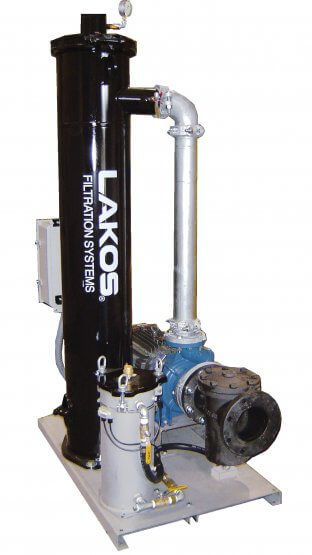
TCX-TCI TowerClean

TCX-TCI System Images

Find a LAKOS HVAC Rep
HVAC Rep Locator

Why Does My Cooling Water Need Filtration?

Cooling Tower High Efficiency
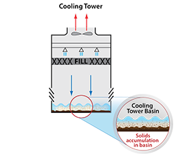
Cooling Tower

Suspended solids clog tower nozzles and water distribution systems – resulting in loss of thermal capacity as well as scale buildup.

Condenser Tube TCX-TCI
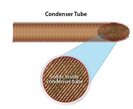
Condenser Tube

Suspended solids reduce heat transfer areas and decrease flow inside tubes by accumulating on internal tube fins.

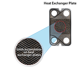
Heat Exchanger Plate

Solids in cooling tower water clog channels and create areas of low thermal conductivity.

Eliminate Basin Cleaning

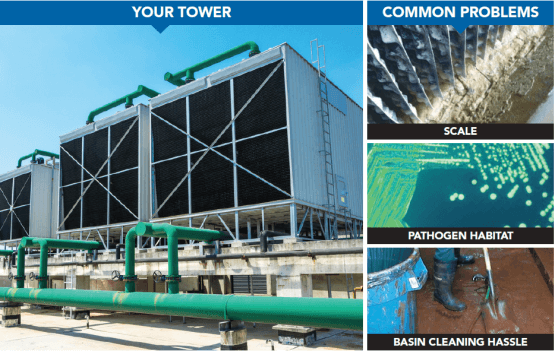
Without filtration, dirt buildup quickly degrades the performance of your cooling tower, leading to increased energy costs and costly cleanouts. Automatic filtration keeps your tower efficient and eliminates cumbersome maintenance. Click Here to learn more about Cooling Tower Water Filtration.

  • Minimize manual cleaning, maintenance and downtime
  • Reduce under-deposit corrosion, remove food source for biological activity, and extend life of the basin
  • Maintain downstream thermal efficiency of heat transfer surfaces
  • Improve water treatment effectiveness
Configure a LAKOS System
Configure Here


Specifications

TCI-TCX
Models
Downloads
(TCI)
Downloads
(TCX)
Flow Inlet
(flanged)
Outlet
(grooved)
Inlet Piping
To Use*
TCI Weight TCX Weight Pump HP Max Basin
Size (Sq. Ft.)
Full Load
Amp. @ 460v
US GPM m3/hr lbs. kg lbs. kg
0030-SRV

0030-ABV

DWG      PDF

DWG      PDF

DWG      PDF

DWG      PDF

30 7 1-1/2″ thd 1″ 2″ 270

219

122

99

270

219

122

99

1 30 2.1
0065-SRV

0065-ABV

DWG      PDF

DWG      PDF

DWG      PDF

DWG      PDF

65 15 2″ thd 1-1/2″ 2-1/2″ 390

323

177

146

390

323

177

146

3 65 4.8
0100-SRV

0100-ABV

DWG      PDF

DWG      PDF

DWG      PDF

DWG      PDF

100 23 3″ 2″ 3″ 452

387

205

176

452

387

205

176

5 100 7.6
0145-SRV

0145-ABV

DWG      PDF

DWG      PDF

DWG      PDF

DWG      PDF

145 33 3″ 2-1/2″ 4″ 475

407

215

185

475

407

215

185

5 145 7.6
0200-SRV

0200-ABV

DWG      PDF

DWG      PDF

DWG      PDF

DWG      PDF

200 45 3″ 3″ 4″ 511

439

232

199

511

439

232

199

7.5 200 11
0280-SRV

0280-ABV

DWG      PDF

DWG      PDF

DWG      PDF

DWG      PDF

280 64 4″ 4″ 6″ 642

569

291

258

642

569

291

258

10 280 14
0400-SRV

0400-ABV

DWG      PDF

DWG      PDF

DWG      PDF

DWG      PDF

400 91 6″ 4″ 6″ 1,065

1,062

483

482

1,065

1,062

483

482

15 400 21
0525-SRV

0525-ABV

DWG      PDF

DWG      PDF

DWG      PDF

DWG      PDF

525 119 6″ 4″ 6″ 1,235

1,199

560

544

1,235

1,199

560

544

20 525 27
0600-SRV

0600-ABV

DWG      PDF

DWG      PDF

DWG      PDF

DWG      PDF

600 136 6″ 6″ 6″ 1,535

1,466

696

543

1,535

1,466

696

543

20 600 27
0825-SRV-L

0825-SRV-V

0825-ABV-L

0825-ABV-V

DWG      PDF

DWG      PDF

DWG      PDF

DWG      PDF

DWG      PDF

DWG      PDF

DWG      PDF

DWG      PDF

825 187 8″ 6″ 8″

2,103

2,232

2,037

954

1,010

924

2,103

2,161

2,037

954

980

924

30 825 40
1100-SRV-L

1100-SRV-V

1100-ABV-L

1100-ABV-V

DWG      PDF

DWG      PDF

DWG      PDF

DWG      PDF

DWG      PDF

DWG      PDF

DWG      PDF

DWG      PDF

1,100 250 8″ 6″ 10″ 2,499

2,163

2,288

2,139

1,134

981

1,038

970

2,147

2,163

2,283

2,139

974

981

1,036

970

40 1,100 52
1670-SRV

1670-ABV

DWG      PDF

DWG      PDF

DWG     PDF

DWG     PDF

1,670 379 10″ 8″ 10″ 3,050

3,074

1,383

1,394

3,050

3,074

1,383

1,394

50 1,670 77

* LAKOS recommended inlet pipe size.
“L” stands for Low-Profile Orientation. “V” stands for Vertical Orientation
All TCX-TCI TowerClean systems are rated for 150 psi (10.3 bar) maximum pressure

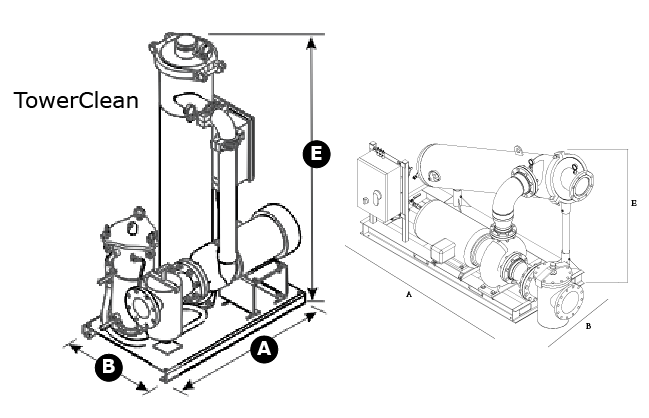
TCX-TCI Dimensions

Dimensions

TCI
Models
Dim A Dim B Dim E – TCI
inches mm inches mm inches mm
0030-SRV

0030-ABV

39-3/4″

39-3/4″

1,010

1,010

24″

24″

610

610

44-5/16″

44-1/4″

1,125

1,124

0065-SRV

0065-ABV

39-3/4″

39-3/4″

1,010

1,010

24″

24″

610

610

44-1/16″

44-1/16″

1,119

1,119

0100-SRV

0100-ABV

39-3/4″

39-3/4″

1,010

1,010

24″

24″

610

610

47″

47″

1,119

1,119

0145-SRV

0145-ABV

39-3/4″

39-3/4″

1,010

1,010

24″

24″

610

610

47-1/2″

47-7/16″

1,207

1,205

0200-SRV

0200-ABV

39-3/4″

39-3/4″

1,010

1,010

24″

24″

610

610

50-1/2″

50-1/2

1,283

1,283

0280-SRV

0280-ABV

39-3/4″

39-3/4″

1,010

1,010

24″

24″

610

610

62″

62″

1,575

1,575

0400-SRV

0400-ABV

48″

48″

1,219

1,219

30″

32″

762

813

69-3/16″

69-3/16″

1,757

1,757

0525-SRV

0525-ABV

48″

48″

1,219

1,219

30″

32″

762

813

69-3/16″

69-3/16″

1,757

1,757

0600-SRV

0600-ABV

60″

60″

1,524

1,524

36″

36″

914

914

84-15/16″

84-15/16″

2,157

2,157

0825-SRV-L

0825-SRV-V

0825-ABV-L

0825-ABV-V

60″

101″

60″

1,524

2,565

1,524

37″

43″

40″

940

1,092

1,016

84-15/16″

56-11/16″

84-15/16″

2,157

1,439

2,157

1100-SRV-L

1100-SRV-V

1100-ABV-L

1100-ABV-V

85-13/16″

60″

98-1/4″

60″

2,180

1,524

2,495

1,524

36″

40″

40″

40″

915

1,016

1,016

1,016

56-11/16″

84-15/16″

56-1/2″

84-15/16″

1,439

2,157

1,435

2,157

1670-SRV-L

1670-ABV-L

117-3/8″

128-5/16″

2,981

3,259

59-3/4″

59-3/4″

1,181

1,517

61-1/8″

61-1/8″

1,553

1,553

“L” stands for Low-Profile Orientation. “V” stands for Vertical Orientation

TCX-TCI Dimensions

Dimensions

TCX
Models
Dim A Dim B Dim E – TCX
inches mm inches mm inches mm
0030-SRV

0030-ABV

39-3/4″

39-3/4″

1,010

1,010

24″

24″

610

610

46-1/8″

46-1/8″

1,172

1,172

0065-SRV

0065-ABV

39-3/4″

39-3/4″

1,010

1,010

24″

24″

610

610

46-1/8″

46-1/8″

1,172

1,172

0100-SRV

0100-ABV

39-3/4″

39-3/4″

1,010

1,010

24″

24″

610

610

48-1/8″

48-1/8″

1,222

1,222

0145-SRV

0145-ABV

39-3/4″

39-3/4″

1,010

1,010

24″

24″

610

610

49-3/8″

49-3/8″

1,254

1,254

0200-SRV

0200-ABV

39-3/4″

39-3/4″

1,010

1,010

24″

24″

610

610

51-3/8″

51-3/8″

1,305

1,305

0280-SRV

0280-ABV

39-3/4″

39-3/4″

1,010

1,010

24″

24″

610

610

67-3/16″

67-3/16″

1,707

1,707

0400-SRV

0400-ABV

48″

48″

1,219

1,219

32″

32″

813

813

69-3/16″

69-3/16″

1,757

1,757

0525-SRV

0525-ABV

48″

48″

1,219

1,219

32″

32″

813

813

69-3/16″

69-3/16″

1,757

1,757

0600-SRV

0600-ABV

60″

60″

1,524

1,524

36″

36″

914

914

84-15/16″

84-15/16″

2,157

2,157

0825-SRV-L

0825-SRV-V

0825-ABV-L

0825-ABV-V

60″

98-1/16″

60″

1,524

2,490

1,524

37″

45″

37″

940

1,143

940

84-15/16″

56-11/16″

84-15/16″

2,157

1,439

2,157

1100-SRV-L

1100-SRV-V

1100-ABV-L

1100-ABV-V

97-5/8″

60″

120-3/16″

60″

2,481

1,524

3,053

1,524

50-7/8″

40″

44″

40″

1,292

1,016

1,118

1,016

56-1/2″

84-15/16″

56-1/2″

84-15/16″

1,435

2,157

1,435

2,157

1670-SRV-L

1670-ABV-L

117-3/8″

128-1/4″

2,981

3,258

46-1/2″

50-1/2″

1,181

1,283

63″

63″

1,600

1,601

“L” stands for Low-Profile Orientation. “V” stands for Vertical Orientation

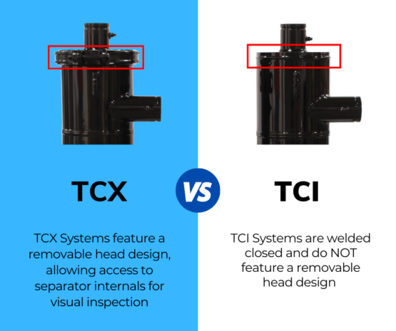
What’s the Difference?

System Adders:
208/230V – 60Hz (PE Motor), 380/415V (50 Hz), 575V (60 Hz), Premium Efficiency (60 Hz Motor)

Inlet/Outlet Valve Kit Adders:
TCV Valve Kit, ECV Valve Kit, 2 Tower Valve Kit

SRV System Adders:
SRI, DEC, Replacement Bags

Pump Repair Kit

ASME

Internal 3M Scotchkote Coating

Stainless Steel Material

Download Brochure
  • LS-710 TCX-TCI TowerClean Brochure
  • LS-580 HVAC Solutions Brochure
Download Manual
  • LS-591 TC-TB Install Guide
Download Sample Spec
  • LS-711 Tower Clean Spec Sheet

Frequently Asked Questions

Answer: As a rule of thumb, LAKOS uses a sizing factor of 1 GPM per square foot of basin area to determine the required size of a Tower Clean (TC) system. Using this factor, multiply the square footage of the cooling tower basin (L x W) by 1 GPM / sq. ft. This gives the basic flow rate for sizing the TC system. Tower Clean literature LS-710 can also be used as a reference for more information and equipment selections.

For industrial applications or very heavy solids loadings, consult LAKOS for recommended basin sweeping flow rates.

TCX-TCI

Answer: LAKOS factory-built purge controllers (ABV, ABV2, AKE, APP, AFS, EFS) do not have factory-set timings. The required purge frequency and durations vary depending on flow rates, solids concentrations, type of solids, etc. The controller time settings must be set at time of installation. LAKOS literature LS-608 can be used to help establish purge duration and frequency based on the application.

Answer: To determine the necessary purge frequency, purge often at first and calculate the proper rate based on the expected volume of separated solids. Purge duration should be long enough to evacuate the purge chamber AND clear the entire length of the purge piping of all solids. This is usually indicated by a change in the color of the purged liquid from dark to light.

The time between purges should never exceed the time it takes to fill 1/3 of the collection chamber volume, based on the expected solids load and the separator’s purge collection volume, as indicated in the separator’s literature. Refer to LS-608 for additional information on calculating purge frequency and duration.

LAKOS Centrifugal Separator Systems, such as TCX/TCI, remove dirt and debris by purging solids from the purge collection chamber (bottom of the Separator). This purge can be either controlled (open/close) via a Automated Ball Valve (ABV) or dumped into a Solids Recovery Vessel (SRV) for water recovery.

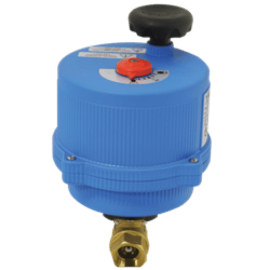
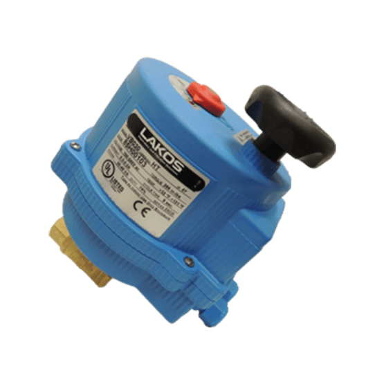
ABV (Automated Ball Valve) opens at pre-programmed intervals to dump purge contents (Dirt and Water) to drain or a collection tank. Learn more here.

SRV (Solids Recovery Vessel) features a bag filter connected to the LAKOS Separator purge that continuously dumps purge contents into a bag filter. This bag filter when filled with dirt can be periodically dumped. Water is recovered by piping the SRV to pump suction. Learn more here.

Answer: While there are many LAKOS Separators still in service after 15-25 years, there are many variables to the longevity of a LAKOS Separator. It can generally be expected to last as long as any other materials of similar construction in that system. Environment, fluid chemical make-up, flow, the material of construction, type of solids, and maintenance purging are all important factors to the life of a separator. It is important to consider all these factors when purchasing a separator. Providing LAKOS with details about your application will ensure your separator meets or exceeds the life expected through your purchase. Consult your LAKOS factory representative to obtain the life expectancy in your specific application.

Answer: Solids-removal efficiency is affected by several factors, including the difference in specific gravity between the solids and the carrying liquid, the viscosity of the liquid, the particle shape, and any purging enhancement techniques. In general, with a specific gravity ratio of 2.6 (e.g. quartz sand in freshwater), liquids of 31 SSU viscosity, and generally round particles, a single pass through a separator predictably removes up to 98% of particles 74 microns (0.0029 inches) and larger. Up to 98% of particles 44 micron and larger for eSeries (eHTX and eJPX) Separators. Appreciable quantities of particles finer than 44 microns (for eSeries Separators) are also removed, as well as particles of lighter specific gravity. Higher specific gravities (like mill scale in water, where SG=5.7) result in much finer levels of filtration.

Recirculating systems (running the fluid through one or more separators continuously) can also result in appreciable removal of particles down as fine as 5 microns.

Contact LAKOS for assistance determining performance expectations on your specific application.

Answer: As a standard, most separators are available in mild carbon steel and 304L/316L-series stainless steels. Specially designed separators can also be constructed in most weldable metals, including, but not limited to: super duplex stainless steels, chrome-moly, titanium, Hastelloy, nickel alloys, and cupronickel. In special cases, separators can also be fabricated in plastic or fiberglass. For materials other than carbon and stainless steel, consult with LAKOS on the availability of your specific material requirements.

Answer: LAKOS Separators and sand media filters are both designed to remove solids from liquids, but have advantages over each other depending on the application.

A separator is designed to remove solids with a specific gravity at least 1.5 times that of the carrying liquid. Separators require very little, if any, maintenance because they have no moving parts. The pressure loss across a separator is predictable and steady and only varies with flow rate. Separators require minimum liquid loss for the purging of collected solids, and can also be equipped with an optional Solids Recovery Vessel that can eliminate liquid loss. However, Separators do not generally help with liquid clarity (turbidity) and are ineffective on organic material, such as algae.

A sand media filter is designed to remove finer solids (down to 5 microns in size) with low specific gravities. Sand filters are used when finer filtration and liquid clarity (turbidity reduction) are a requirement. Sand filters do require more operational maintenance (more moving parts) and use more liquid for backwashing of the sand bed to remove the collected solids. Pressure loss across a media filter varies, as solids are collected and enter a backwash cycle when they reach a predetermined pressure loss. However, sand media filters are very efficient at removing a wide variety of light, organic solids.

Answer: The maximum solids loading on LAKOS Separators is recommended to be less than 1% by volume. While 1% may seem low, keep in mind that 1% in a small 100 GPM system is 1 gallon of solids every minute, or 1,440 gallons (twenty-six 55-gallon drums) of solids per day. If your application exceeds these limitations, please consult your factory representative for proven alternatives.

Answer: Standard maximum temperature rating for operating most LAKOS Separators is 180°F. LAKOS can easily accommodate higher temperatures with custom separators.

Answer: The LAKOS Separator is capable of working with any liquid that has a viscosity less than 100 SSU. The solids to be separated must also have a specific gravity at least 1.5x greater than the fluid. The greater the specific gravity of the separable solids and the lower the viscosity of the liquid, the better the LAKOS Separator will work. A good rule of thumb: if the solids settle within 3-4 minutes in your liquid, they will likely be separable with a LAKOS Separator.

Answer: Standard maximum pressure rating for most LAKOS Separators is 150 psi. Contact the factory for higher pressures; LAKOS can accommodate pressures up to 3000 psi through custom separators.

Answer: Yes, we can manufacture a separator with a Canadian Registration Number (CRN). We must know the Province or Territory the vessel is to be located so we can contact the registration controlling agency within that Province or Territory to determine the cost and lead time. Customer’s who require CRN should notify us in writing at time of order. We cannot provide CRN during the manufacturing process or after it is shipped.