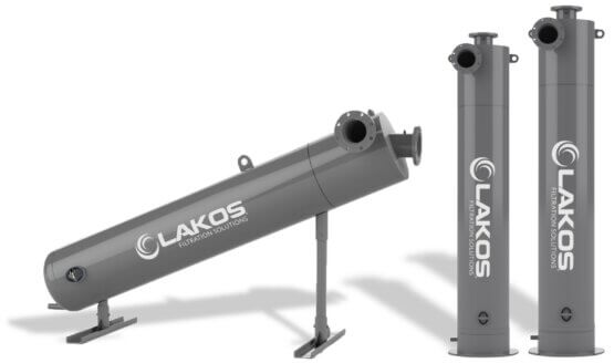
*PWC-L default inlet position is now in the 3 or 9 o’clock position.

| Models* | Downloads | Flow Rates** | Inlet/ Outlet 150# ANSI Flanges |
Purge Size Male, NPT |
Collection Chamber Capacity |
Ship Weight | |||
| US GPM | m3/hr | gal. | liters | lbs. | kg | ||||
| PWC-1040-L PWC-1040-V |
DWG PDF DWG PDF |
240-540 | 55-123 | 4″ | 1-1/2″ | 0.8 1.6 |
3.1 5.9 |
547 495 |
248 224 |
| PWC-1050-L PWC-1050-V |
DWG PDF DWG PDF |
370-820 | 84-186 | 6″ | 1-1/2″ | 0.7 3.0 |
2.5 11.2 |
775 752 |
351 341 |
| PWC-1060-L PWC-1060-V |
DWG PDF DWG PDF |
550-1,200 | 125-273 | 6″ | 1-1/2″ | 1.3 6.4 |
4.8 24.3 |
1,108 1,103 |
502 500 |
| PWC-1080-L PWC-1080-V |
DWG PDF DWG PDF |
940-2,060 | 213-468 | 8″ | 1-1/2″ | 2.1 7.8 |
8.1 29.4 |
1,694 1,689 |
768 766 |
| PWC-10120-L PWC-10120-V |
DWG PDF DWG PDF |
1,800-4,000 | 409-908 | 12″ | 2″ | 13.7 62.2 |
51.9 235.5 |
5,187 5,382 |
2,353 2,441 |
PWC-L default inlet position is now in the 3 or 9 o’clock position. “L” drawings are oriented in the 9 o’clock position, for other orientations Consult Factory.
* Models ending with “L” are low profile; “V” are vertical profile.
** Flow range is critical to separator performance. Do not oversize separator or use pipe size for model selection.
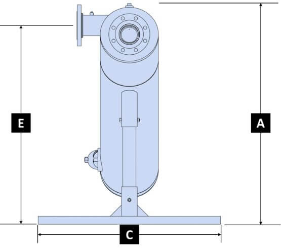
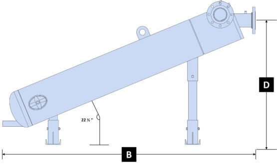
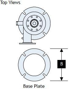
| Models | Dim A | Dim B | Dim C | Dim D | Dim E* | |||||
| inches | mm | inches | mm | inches | mm | inches | mm | inches | mm | |
| PWC-1040-L | 48″ | 1230 | 84″ | 2142 | 40″ | 1016 | 41-9/16″ | 1056 | 43-1/2″ | 1105 |
| PWC-1050-L | 54″ | 1393 | 93″ | 2374 | 40″ | 1016 | 46-15/16″ | 1192 | 48-7/8″ | 1241 |
| PWC-1060-L | 66″ | 1687 | 112″ | 2845 | 40″ | 1016 | 56-3/8″ | 1432 | 60-3/16″ | 1528 |
| PWC-1080-L | 80″ | 2037 | 138″ | 3523 | 40″ | 1016 | 68-3/16″ | 1733 | 72-1/4″ | 1836 |
| PWC-10120-L | 114-5/8″ | 2905 | 198-13/16″ | 5023 | 60″ | 1524 | 97-1/4″ | 2471 | 103-15/16″ | 2644 |
*PWC-L default inlet position is now in the 3 or 9 o’clock position. Dimensions shown are for the 9 o’clock position. Consult factory for other layouts.
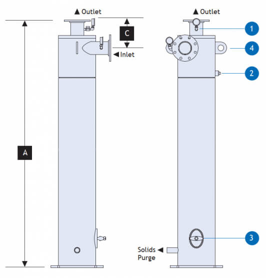
| Models | Dim A | Dim B | Dim C | |||
| inches | mm | inches | mm | inches | mm | |
| PWC-1040-V | 85″ | 2151 | 18″ | 457 | 10″ | 244 |
| PWC-1050-V | 101″ | 2581 | 22″ | 559 | 11″ | 284 |
| PWC-1060-V | 122″ | 3115 | 26″ | 660 | 11″ | 284 |
| PWC-1080-V | 144″ | 3661 | 32″ | 813 | 13″ | 333 |
| PWC-10120-V | 218-1/16″ | 5538 | 44″ | 1118 | 15-7/8″ | 403 |
Answer: Flow rate is the most important factor in determining separator size because all LAKOS Separators operate within a prescribed flow range. Pipe size is not a factor in model selection so do not use your existing pipe size to determine the separator size. Required separator size is often, but not always, smaller than the existing piping, and appropriate hardware is used to match the inlet/outlet size with existing piping.
Answer: To determine the necessary purge frequency, purge often at first and calculate the proper rate based on the expected volume of separated solids. Purge duration should be long enough to evacuate the purge chamber AND clear the entire length of the purge piping of all solids. This is usually indicated by a change in the color of the purged liquid from dark to light. The time between purges should never exceed the time it takes to fill 1/3 of the collection chamber volume, based on the expected solids load and the separator’s purge collection volume, as indicated in the separator’s literature. Refer to LS-608 for additional information on calculating purge frequency and duration.
Answer: While there are many LAKOS Separators still in service after 15-25 years, there are many variables to the longevity of a LAKOS Separator. It can generally be expected to last as long as any other materials of similar construction in that system. Environment, fluid chemical make-up, flow, the material of construction, type of solids, and maintenance purging are all important factors to the life of a separator. It is important to consider all these factors when purchasing a separator. Providing LAKOS with details about your application will ensure your separator meets or exceeds the life expected through your purchase. Consult your LAKOS factory representative to obtain the life expectancy in your specific application.
Answer: The maximum solids loading on LAKOS Separators is recommended to be less than 1% by volume. While 1% may seem low, keep in mind that 1% in a small 100 GPM system is 1 gallon of solids every minute, or 1,440 gallons (twenty-six 55-gallon drums) of solids per day. SMP Separators for residential use are not recommended to exceed 0.25% by volume. ILB Series Separators are not recommended to exceed 0.50% by volume. If your application exceeds these limitations, please consult your factory representative for proven alternatives.
Answer: Standard maximum temperature rating for operating most LAKOS Separators is 180°F. The exceptions are SMP Separators, which have a maximum temperature of 120°F. LAKOS can easily accommodate higher temperatures with custom separators.
Answer: Standard maximum pressure rating for most LAKOS Separators is 150 psi. The exceptions are the SMP Separators, which have a maximum pressure rating of 100 psi. Contact the factory for higher pressures; LAKOS can accommodate pressures up to 3000 psi through custom separators.
Answer: Yes, we can manufacture a separator with a Canadian Registration Number (CRN). We must know the Province or Territory the vessel is to be located so we can contact the registration controlling agency within that Province or Territory to determine the cost and lead time.