HTX-HTH Standard Efficiency Separator
Find a LAKOS HVAC Rep
HVAC Rep Locator
Configure a LAKOS Separator
Click Here
Specifications (HTX)
| Models | Downloads | Flow Range | Inlet/Outlet Grooved Coupling** |
Purge Size Male NPT |
Collection Chamber Capacity |
Weight | |||
| US GPM | m3/hr | gal. | liters | lbs. | kg | ||||
| HTX-0016 | DWG PDF | 16-30 | 4-7 | 1″ | 3/4″ | 0.2 | 0.8 | 45 | 20 |
| HTX-0028 | DWG PDF | 28-45 | 7-10 | 1-1/4″ | 3/4″ | 0.5 | 1.8 | 69 | 31 |
| HTX-0038 | DWG PDF | 38-65 | 9-15 | 1-1/2″ | 3/4″ | 0.7 | 2.8 | 92 | 42 |
| HTX-0060 | DWG PDF | 60-100 | 14-23 | 2″ | 3/4″ | 1.4 | 5.4 | 160 | 73 |
| HTX-0085 | DWG PDF | 85-145 | 19-33 | 2-1/2″ | 3/4″ | 1.4 | 5.4 | 202 | 92 |
| HTX-0130 | DWG PDF | 130-255 | 30-51 | 3″ | 3/4″ | 1.5 | 5.6 | 214 | 97 |
| HTX-0200-L | DWG PDF | 200-325 | 45-74 | 4″ | 3/4″ | 1.0 | 3.8 | 408 | 185 |
| HTX-0200-V | DWG PDF | 200-325 | 45-74 | 4″ | 3/4″ | 2.6 | 9.8 | 381 | 173 |
| HTX-0285-L | DWG PDF | 285-525 | 65-120 | 4″ | 1-1/2″ | 2.1 | 7.9 | 476 | 216 |
| HTX-0285-V | DWG PDF | 285-525 | 65-120 | 4″ | 1-1/2″ | 5.4 | 20.5 | 420 | 191 |
| HTX-0450-L | DWG PDF | 450-825 | 102-187 | 6″ | 1-1/2″ | 2.8 | 10.6 | 634 | 288 |
| HTX-0450-V | DWG PDF | 450-825 | 102-187 | 6″ | 1-1/2″ | 6.7 | 25.4 | 593 | 269 |
| HTX-0500-L | DWG PDF | 500-1,100 | 114-250 | 6″ | 1-1/2″ | 2.8 | 10.6 | 642 | 291 |
| HTX-0500-V | DWG PDF | 500-1,100 | 114-250 | 6″ | 1-1/2″ | 6.7 | 25.4 | 600 | 272 |
| HTX-0810-L | DWG PDF | 810-1,670 | 184-379 | 8″ | 1-1/2″ | 6.2 | 23.5 | 760 | 345 |
| HTX-0810-V | DWG PDF | 810-1,670 | 184-379 | 8″ | 1-1/2″ | 12.5 | 47.3 | 786 | 357 |
| HTX-1275-L | DWG PDF | 1,275-3,100 | 290-704 | 10″ | 2″ | 11.5 | 43.5 | 1,064 | 483 |
| HTX-1275-V | DWG PDF | 1,275-3,100 | 290-704 | 10″ | 2″ | 24.0 | 90.8 | 1,092 | 495 |
| HTX-1950-L | DWG PDF | 1,950-4,350 | 443-988 | 12″ | 2″ | 15.0 | 56.8 | 1,351 | 613 |
| HTX-1950-V | DWG PDF | 1,950-4,350 | 443-988 | 12″ | 2″ | 31.5 | 119.2 | 1,312 | 595 |
| HTX-3500-L | DWG PDF | 3,500-6,800 | 795-1,545 | 16″ | 2″ | 50.6 | 191.5 | 4,360 | 1,978 |
| HTX-3500-V | DWG PDF | 3,500-6,800 | 795-1,545 | 16″ | 2″ | 99.3 | 375.9 | 4,020 | 1,823 |
| HTX-6700-L | DWG PDF | 6,700-12,750 | 1,522-2,895 | 20″ | 2″ | 81.0 | 306.6 | 7,901 | 3,584 |
| HTX-6700-V | DWG PDF | 6,700-12,750 | 1,522-2,895 | 20″ | 2″ | 162.3 | 614.4 | 7,475 | 3,391 |
Specifications (HTH)
| Models | Downloads | Flow Range | Inlet/Outlet Grooved Coupling** |
Purge Size Male NPT |
Collection Chamber Capacity |
Weight | |||
| US GPM | m3/hr | gal. | liters | lbs. | kg | ||||
| HTH-0285-L | DWG PDF | 285-525 | 65-120 | 4″ | 1-1/2″ | 2.1 | 7.9 | 445 | 202 |
| HTH-0285-V | DWG PDF | 285-525 | 65-120 | 4″ | 1-1/2″ | 3.8 | 14.4 | 387 | 176 |
| HTH-0450-L | DWG PDF | 450-825 | 100-190 | 6″ | 1-1/2″ | 2.8 | 10.6 | 591 | 268 |
| HTH-0450-V | DWG PDF | 450-825 | 100-190 | 6″ | 1-1/2″ | 5.6 | 21.2 | 548 | 249 |
| HTH-0500-L | DWG PDF | 500-1,100 | 115-250 | 6″ | 1-1/2″ | 2.8 | 10.6 | 598 | 271 |
| HTH-0500-V | DWG PDF | 500-1,100 | 115-250 | 6″ | 1-1/2″ | 5.6 | 21.2 | 556 | 252 |
| HTH-0810-L | DWG PDF | 810-1,670 | 185-380 | 8″ | 1-1/2″ | 6.2 | 23.5 | 674 | 306 |
| HTH-0810-V | DWG PDF | 810-1,670 | 185-380 | 8″ | 1-1/2″ | 9.1 | 34.4 | 698 | 317 |
| HTH-1275-L | DWG PDF | 1,275-3,100 | 290-705 | 10″ | 2″ | 11.5 | 43.5 | 894 | 406 |
| HTH-1275-V | DWG PDF | 1,275-3,100 | 290-705 | 10″ | 2″ | 21.8 | 82.5 | 920 | 417 |
| HTH-1950-L | DWG PDF | 1,950-4,350 | 440-990 | 12″ | 2″ | 15.0 | 56.8 | 1,095 | 497 |
| HTH-1950-V | DWG PDF | 1,950-4,350 | 440-990 | 12″ | 2″ | 30.0 | 113.6 | 1,175 | 533 |
| HTH-3500-L | DWG PDF | 3,500-6,800 | 795-1,545 | 16″ | 2″ | 50.6 | 191.5 | 2,949 | 1,338 |
| HTH-3500-V | DWG PDF | 3,500-6,800 | 795-1,545 | 16″ | 2″ | 81.3 | 307.8 | 2,591 | 1,175 |
| HTH-6700-L | DWG PDF | 6,700-12,750 | 1,522-2,895 | 20″ | 2″ | 81.0 | 306.6 | 6,023 | 2,732 |
| HTH-6700-V | DWG PDF | 6,700-12,750 | 1,522-2,895 | 20″ | 2″ | 62.0 | 613.2 | 5,608 | 2,544 |
** Inlet/ Outlet may also be specified with ANSI flanges, DIN flanges, BSP threads or JIS threads
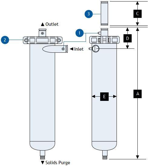
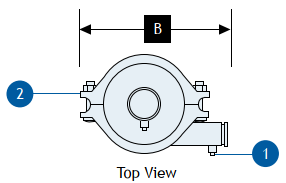
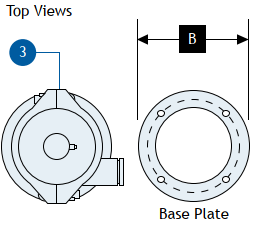
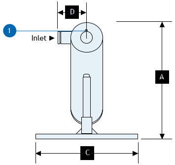
Dimensions Low Flow Rate (HTX)
| Models | Dim A | Dim B | Dim C | Dim D | Dim E | |||||
| inches | mm | inches | mm | inches | mm | inches | mm | inches | mm | |
| HTX-0016 | 33-3/16″ | 843 | 9-13/16″ | 249 | 7″ | 178 | 7-15/16″ | 202 | 4-1/2″ | 114 |
| HTX-0028 | 35″ | 889 | 12-5/16″ | 313 | 7″ | 178 | 8-1/16″ | 205 | 5-9/16″ | 141 |
| HTX-0038 | 37-9/16″ | 954 | 12-1/2″ | 318 | 8″ | 203 | 8-1/8″ | 206 | 6-5/8″ | 168 |
| HTX-0060 | 46-13/16″ | 1,189 | 15-4/4″ | 400 | 11″ | 279 | 8-1/8″ | 206 | 8-5/8″ | 219 |
| HTX-0085 | 54-3/8″ | 1,387 | 15-3/4″ | 400 | 15″ | 381 | 9-5/8″ | 244 | 8-5/8″ | 219 |
| HTX-0130 | 57-3/4″ | 1,467 | 15-3/4″ | 400 | 16″ | 406 | 10-1/2″ | 267 | 8-5/8″ | 219 |
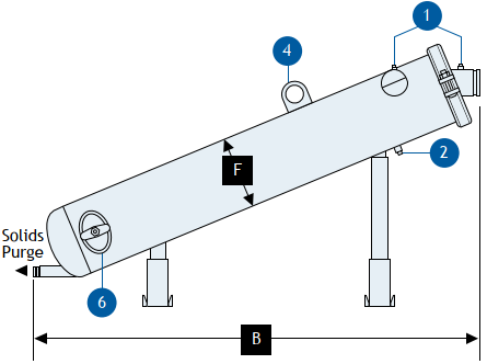
Dimensions (HTX-L)
| Models | Dim A | Dim B | Dim C | Dim E | Dim F | |||||
| inches | mm | inches | mm | inches | mm | inches | mm | inches | mm | |
| HTX-0200-L | 40-11/16″ | 1,033 | 64-3/4″ | 1,645 | 40″ | 1,016 | 11″ | 279 | 10-3/4″ | 273 |
| HTX-0285-L | 44″ | 1,118 | 70-1/16″ | 1,780 | 40″ | 1,016 | 11″ | 379 | 12-3/4″ | 324 |
| HTX-0450-L | 51-1/2″ | 1,308 | 85-1/6″ | 2,161 | 40″ | 1,016 | 12″ | 305 | 14″ | 356 |
| HTX-0500-L | 51-1/2″ | 1,308 | 85-1/6″ | 2,161 | 40″ | 1,016 | 12″ | 305 | 14″ | 356 |
| HTX-0810-L | 57-5/16″ | 1,456 | 92-7/8″ | 2,357 | 40″ | 1,016 | 14″ | 356 | 18″ | 457 |
| HTX-1275-L | 72-7/16″ | 1,840 | 118-13/16″ | 3,018 | 40″ | 1,016 | 18″ | 457 | 22″ | 559 |
| HTX-1950-L | 79-5/8″ | 2,022 | 130-3/4″ | 3,321 | 40″ | 1,016 | 18″ | 457 | 24″ | 610 |
| HTX-3500-L | 111-3/4″ | 2,838 | 189-1/2″ | 4,813 | 60″ | 1,524 | 26″ | 660 | 36″ | 914 |
| HTX-3500-L | 131-3/4″ | 3,346 | 226-9/16″ | 5,755 | 60″ | 1,524 | 30″ | 762 | 42″ | 1,067 |
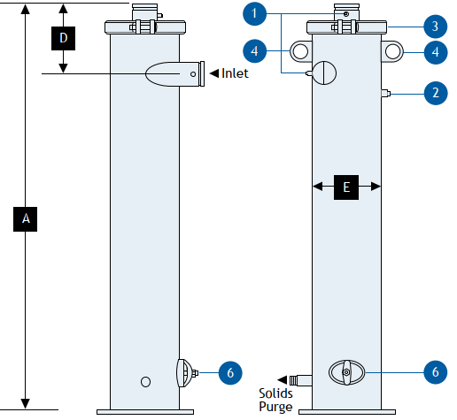
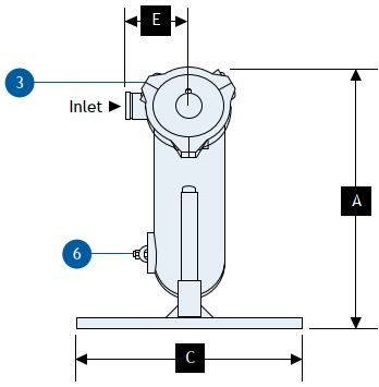
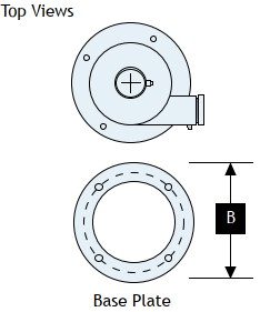
Dimensions (HTX-V)
| Models | Dim A | Dim B | Dim D | Dim E | ||||
| inches | mm | inches | mm | inches | mm | inches | mm | |
| HTX-0200-V | 74-1/16″ | 1,881 | 16″ | 406 | 11-3/4″ | 298 | 10-3/4″ | 273 |
| HTX-0285-V | 66-9/16″ | 1,691 | 18″ | 457 | 14-3/16″ | 360 | 12-3/4″ | 324 |
| HTX-0450-V | 82-5/16″ | 2,091 | 20″ | 508 | 13-3/8″ | 340 | 14″ | 356 |
| HTX-0500-V | 82-5/16″ | 2,091 | 20″ | 508 | 13-3/8″ | 340 | 14″ | 356 |
| HTX-0810-V | 91″ | 2,311 | 26″ | 660 | 16-7/16″ | 418 | 18″ | 457 |
| HTX-1275-V | 117-3/16″ | 2,972 | 30″ | 762 | 18-1/2″ | 470 | 22″ | 559 |
| HTX-1950-V | 129-7/8″ | 3,299 | 32″ | 813 | 18-11/16″ | 475 | 24″ | 610 |
| HTX-3500-V | 184-1/16″ | 4,675 | 42″ | 1,067 | 39-1/8″ | 994 | 36″ | 762 |
| HTX-6700-V | 220-1/4″ | 5,594 | 52″ | 1,321 | 42″ | 1,067 | 42″ | 1,067 |
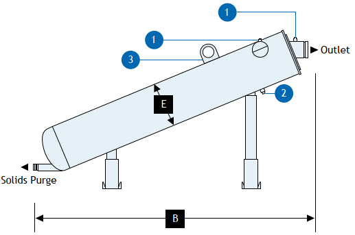
Dimensions (HTH-L)
| Models | Dim A | Dim B | Dim C | Dim D | Dim E | |||||
| inches | mm | inches | mm | inches | mm | inches | mm | inches | mm | |
| HTH-0285-L | 41-13/16″ | 1,062 | 70-3/16″ | 1,783 | 40″ | 1,016 | 11″ | 279 | 12-3/4″ | 324 |
| HTH-0450-L | 49-1/8″ | 1,248 | 85″ | 2,195 | 40″ | 1,016 | 12″ | 305 | 14″ | 356 |
| HTH-0500-L | 49-1/8″ | 1,248 | 85″ | 2,195 | 40″ | 1,016 | 12″ | 305 | 14″ | 356 |
| HTH-0810-L | 54-5/8″ | 1,387 | 92-13/16″ | 2,357 | 40″ | 1,016 | 18-7/8″ | 479 | 18″ | 457 |
| HTH-1275-L | 68-1/2″ | 1,740 | 118-13/16″ | 3,018 | 40″ | 1,016 | 18″ | 457 | 22″ | 559 |
| HTH-1950-L | 74-3/32″ | 1,882 | 130″ | 3,302 | 40″ | 1,016 | 18″ | 457 | 24″ | 610 |
| HTH-3500-L | 105-5/16″ | 2,675 | 189-7/16″ | 4,812 | 60″ | 1,524 | 26″ | 660 | 36″ | 914 |
| HTH-6700-L | 125″ | 3,175 | 225″ | 5,715 | 60″ | 1,524 | 30″ | 762 | 42″ | 1,067 |
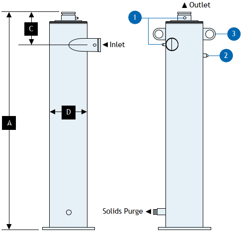
Dimensions (HTH-V)
| Models | Dim A | Dim B | Dim C | Dim D | ||||
| inches | mm | inches | mm | inches | mm | inches | mm | |
| HTH-0285-V | 66-9/16″ | 1,691 | 18″ | 457 | 14-3/16″ | 360 | 12-3/4″ | 324 |
| HTH-0450-V | 52-5/16″ | 2,091 | 20″ | 508 | 13-3/8″ | 317 | 14″ | 356 |
| HTH-0500-V | 82-5/16″ | 2,091 | 20″ | 508 | 13-3/8″ | 317 | 14″ | 356 |
| HTH-0810-V | 91″ | 2,311 | 26″ | 660 | 16-7/16″ | 418 | 18″ | 457 |
| HTH-1275-V | 117-3/16″ | 2,977 | 30″ | 762 | 18-1/2″ | 470 | 22″ | 559 |
| HTH-1950-V | 129-15/16″ | 3,300 | 32″ | 812 | 18-3/4″ | 476 | 24″ | 610 |
| HTH-3500-V | 180-15/16″ | 4,596 | 44″ | 1,118 | 37″ | 940 | 36″ | 914 |
| HTH-6700-V | 218-1/4″ | 5,444 | 48″ | 1,219 | 40-7/16″ | 1,027 | 42″ | 1,067 |
Purging Adders (Solids Recovery Options):
SRV/CRS, SRI/IPS, DEC, Replacement Bags
Purging Adders (Purge Options):
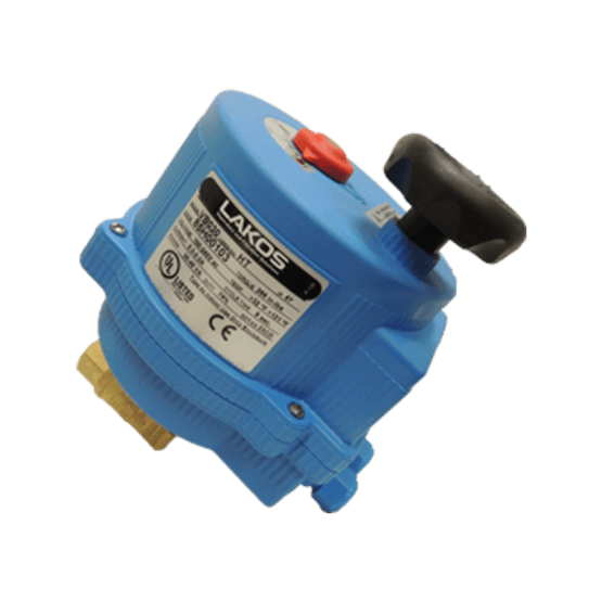
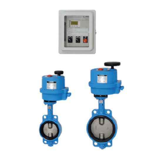
Electric Ball Valve (ABV) or Electric Fail-Safe Ball Valves (EFS)
Accessories and Adders:
Pressure Gauge Kit (IKT), Grooved Coupling Spools, Grooved Couplings, Welded-On Flanges
ASME
Internal 3M Scotchkote Coating
Stainless Steel Material
Download Brochure
-
LS-624 HTH Brochure
-
LS-625 HTX Brochure
-
LS-580 HVAC Solutions Brochure
-
LS-728 HTX Seperator Efficiency
Download Manual
Download Sample Spec
-
LS-042 HTH Spec Sheet
-
LS-043 HTX Spec Sheet
Frequently Asked Questions
Answer: Flow rate is the most important factor in determining separator size because all LAKOS Separators operate within a prescribed flow range. Pipe size is not a factor in model selection so do not use your existing pipe size to determine the separator size. Required separator size is often, but not always, smaller than the existing piping, and appropriate hardware is used to match the inlet/outlet size with existing piping.
Answer: LAKOS factory-built purge controllers (ABV, ABV2, AKE, APP, AFS, EFS) do not have factory-set timings. The required purge frequency and durations vary depending on flow rates, solids concentrations, type of solids, etc. The controller time settings must be set at installation and LAKOS literature LS-608 can be used to help establish purge duration and frequency based on the application.
Answer: To determine the necessary purge frequency, purge often at first and calculate the proper rate based on the expected volume of separated solids. Purge duration should be long enough to evacuate the purge chamber AND clear the entire length of the purge piping of all solids. This is usually indicated by a change in the color of the purged liquid from dark to light. The time between purges should never exceed the time it takes to fill 1/3 of the collection chamber volume, based on the expected solids load and the separator’s purge collection volume, as indicated in the separator’s literature. Refer to LS-608 for additional information on calculating purge frequency and duration.
Answer: While there are many LAKOS Separators still in service after 15-25 years, there are many variables to the longevity of a LAKOS Separator. It can generally be expected to last as long as any other materials of similar construction in that system. Environment, fluid chemical make-up, flow, the material of construction, type of solids, and maintenance purging are all important factors to the life of a separator. It is important to consider all these factors when purchasing a separator. Providing LAKOS with details about your application will ensure your separator meets or exceeds the life expected through your purchase. Consult your LAKOS factory representative to obtain the life expectancy in your specific application.
Answer: Solids-removal efficiency is affected by several factors, including the difference in specific gravity between the solids and the carrying liquid, the viscosity of the liquid, the particle shape, and any purging enhancement techniques. In general, with a specific gravity ratio of 2.6 (e.g. quartz sand in freshwater), liquids of 31 SSU viscosity, and generally round particles, a single pass through a separator predictably removes 98% of particles 74 microns (0.0029 inches) and larger. Appreciable quantities of particles finer than 74 microns are also removed, as well as particles of lighter specific gravity. Higher specific gravities (like mill scale in water, where SG=5.7) result in much finer levels of filtration.
Recirculating systems (running the fluid through one or more separators continuously) can also result in appreciable removal of particles down as fine as 5 microns.
Contact LAKOS for assistance determining performance expectations on your specific application.
Answer: As a standard, most separators are available in mild carbon steel and 304L/316L-series stainless steels. Specially designed separators can also be constructed in most weldable metals, including, but not limited to: super duplex stainless steels, chrome-moly, titanium, Hastelloy, nickel alloys, and cupronickel. In special cases, separators can also be fabricated in plastic or fiberglass. For materials other than carbon and stainless steel, consult with LAKOS on the availability of your specific material requirements.
Answer: The maximum solids loading on LAKOS Separators is recommended to be less than 1% by volume. While 1% may seem low, keep in mind that 1% in a small 100 GPM system is 1 gallon of solids every minute, or 1,440 gallons (twenty-six 55-gallon drums) of solids per day. SMP Separators for residential use are not recommended to exceed 0.25% by volume. ILB Series Separators are not recommended to exceed 0.50% by volume. If your application exceeds these limitations, please consult your factory representative for proven alternatives.
Answer: The LAKOS Separator is capable of working with any liquid that has a viscosity less than 100 SSU. The solids to be separated must also have a specific gravity at least 1.5 greater than the fluid. The greater the specific gravity of the separable solids and the lower the viscosity of the liquid, the better the LAKOS Separator will work. A good rule of thumb: if the solids settle within 3-4 minutes in your liquid, they will likely be separable with a LAKOS Separator.
Answer: Standard maximum temperature rating for operating most LAKOS Separators is 180°F. The exceptions are SMP Separators, which have a maximum temperature of 120°F. LAKOS can easily accommodate higher temperatures with custom separators.
Answer: Standard maximum pressure rating for most LAKOS Separators is 150 psi. The exceptions are the SMP Separators, which have a maximum pressure rating of 100 psi. Contact the factory for higher pressures; LAKOS can accommodate pressures up to 3000 psi through custom separators.
Answer: Yes, we can manufacture a separator with a Canadian Registration Number (CRN). We must know the Province or Territory the vessel is to be located so we can contact the registration controlling agency within that Province or Territory to determine the cost and lead time.