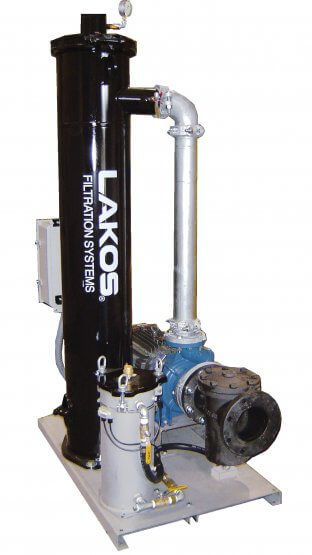
Packaged Separator Systems for Cooling Towers & Remote Sumps
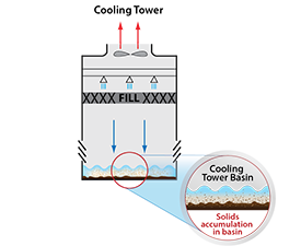
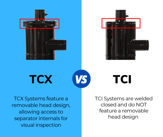
LAKOS TCX-TCI Cooling Tower Basin Cleaning filtration systems remove fine solids (44 microns and larger) from HVAC open and closed loops. This packaged system reduces manual basin cleaning, equipment operating costs, maintenance costs, and water use.
- Filter performance rated to remove up to 98% of solids, 74 microns and larger, and up to 99% of solids 44 microns and larger in recirculating applications.
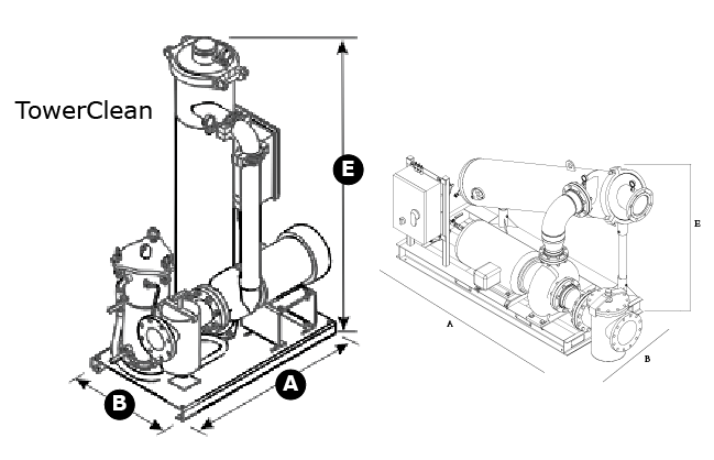
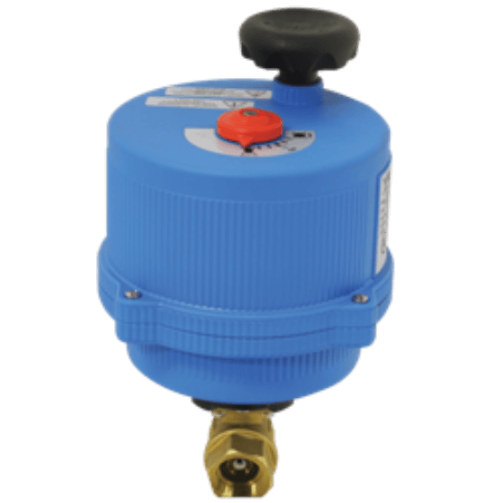
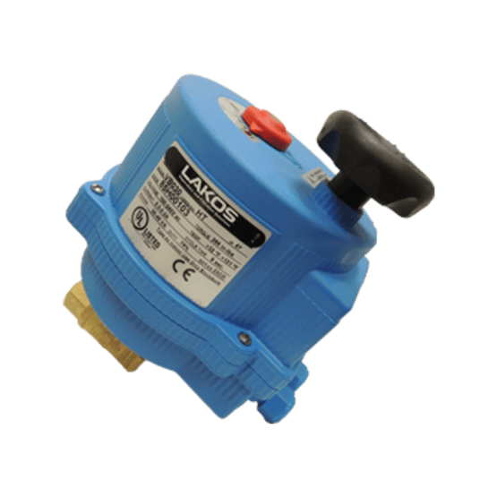
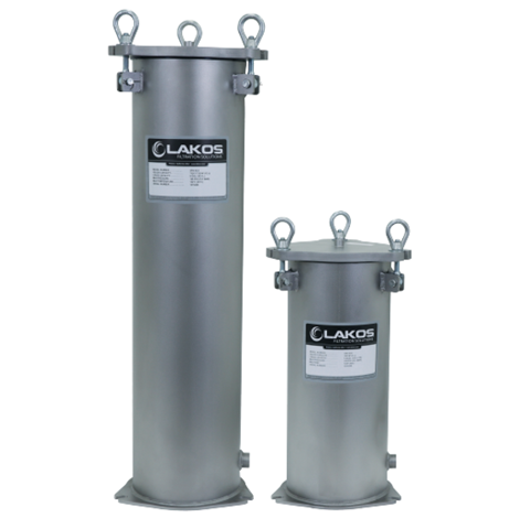
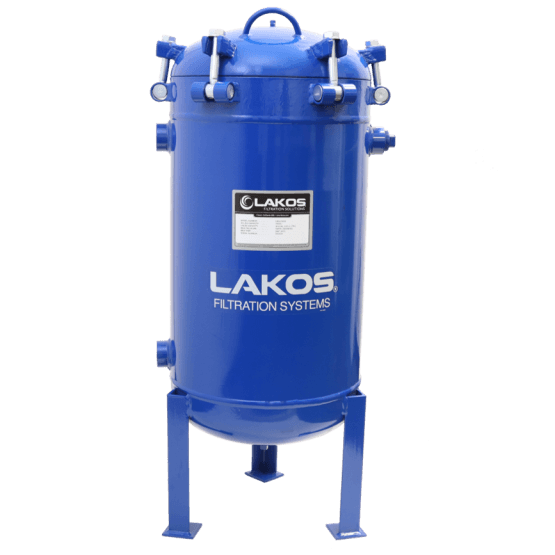
- TCX-TCI Systems include a Lakos Standard Efficiency Separator, High-Efficiency pump, standard capacity (6 liters) Solids Recovery Vessel and/or Automated Purge Valve.
- TCX-TCI systems are designed with a high head pump to effectively sweep and remove troublesome solids from Cooling Tower Basins.
Flow Range: 30 – 1,670 US GPM (7 – 379 m³/hr)
Maximum Pressure: 150 psi (10.3 bar)